ClockGlomerate
Background
In a world filled with monotonous touch interfaces, I thoroughly enjoy the rare instances where I get to experience the smooth turn of a knob or the satisfying click of a firm toggle switch.
One could argue that the pinnacle of mechanical inputs is the majestic rotary dial. To experience the joy of spinning a rotary dial as frequently as possible, it was paramount that I incorporate one into a project. Therefore I decided to build a clock using a rotary telephone’s dial as the interface.
As is typical for these types of things, more time passed, and more excessive “features” were added for good measure.
Prototyping
Interfacing with the rotary dial
The first order of business was to detect a user’s dialed input. There are two pairs of contacts on the dial that act as switches. The first pair is closed when the dial is in its resting position and opens when the dial is being turned. The second pair opens and closes while the dial is in the process of spinning back to its rest position. The number of times the contacts open and close depends on how far the dial spins. For instance, dialing the digit 8 will result in the contacts opening and closing 8 times on its journey back to the rest position.
Warning: annoying continuity tone
By connecting these switches to a microcontroller along with the requisite pull-up resistors, we can digitize the dialed input.
Driving LEDs
I began by working with two MAX7219 LED driver chips and an Arduino. I chose the MAX7219 because there was this nice existing library and tutorial. A single MAX7219 IC can drive 84 LEDs and the LedControl library supports chaining up to 8 drivers together. My design uses 109 LEDs, thus requiring 2 LED drivers.
Keeping time
To keep accurate time used a ChronoDot real time clock (RTC), which is essentially a breakout board for the DS3231 chip. The DS3231 maintains accurate time using a temperature compensated crystal oscillator, keeps track of the date including how many days are in each month, and has the ability to store 2 alarms.
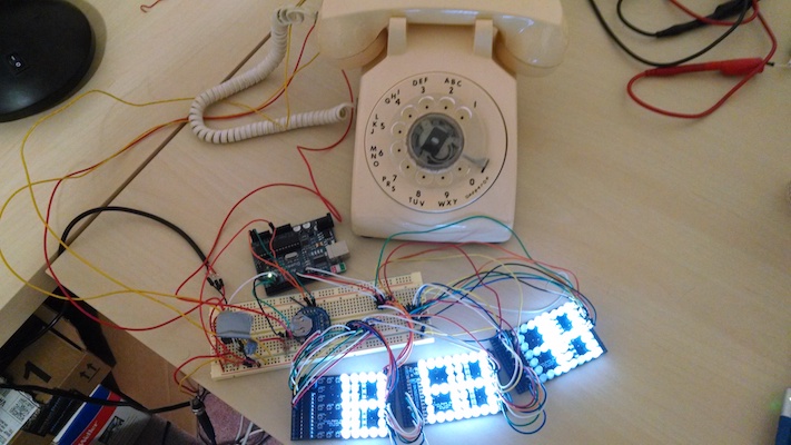
Initial test
I wired up 2 digits worth of LEDs and ran some test code. The Arduino, MAX7219 driver, and RTC all worked, thus the foundation for the clock had been laid!
Counting!
Prototype PCB
To start hashing out how the interface was going to work, it was time to hook up the rotary dial as an input and connect 6 digits worth of LEDs. I decided to make a PCB because hand wiring 100+ LEDs to a breadboard is tedious and can get messy in a hurry.
I usually choose OSH Park to manufacture my PCBs because they are both high quality and tend have the lowest prices if you’re willing to wait 2 weeks. Prices are based on board area, and the minimum order quantity is 3. As a challenge to minimize cost and waste, I designed a single circuit board that could serve as 3 different circuits depending on which components were populated and what jumper pads were bridged. I chained together the 3 PCBs and had a working 6 digit display to play around with.
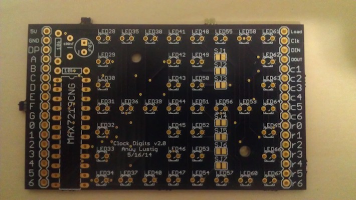
A single PCB with 3 configurations
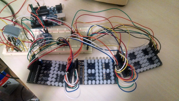
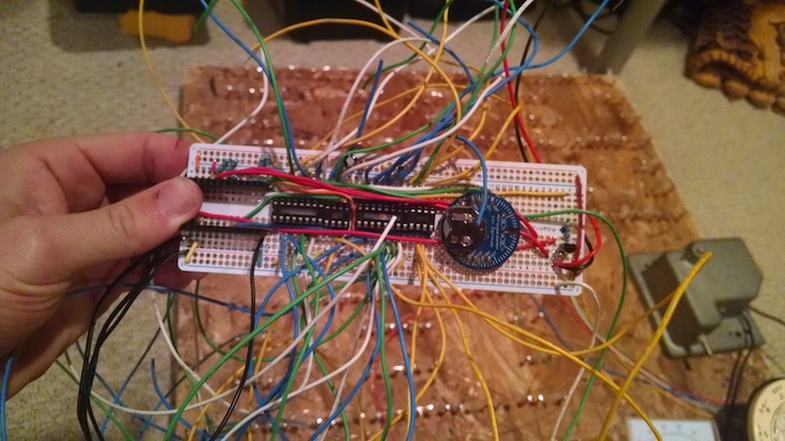
Wired up with jumper wires and a breadboard
Test display
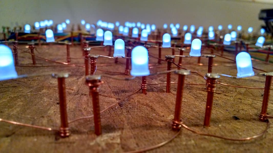
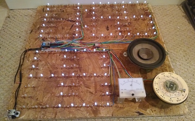
Constructing the clock
I wanted the clock to be fairly large and look interesting. At some point I learned that the reason breadboards are called breadboards is because people used to prototype circuits by wrapping wire around nails that were stuck into a wooden breadboard. I thought it would be cool looking to wire up the LEDs in the original breadboard fashion so I got a 2’ x 2’ wooden panel, some copper nails, and some bare copper wire. After a lot of hammering, wire wrapping, and soldering, I had a 6 digit display. To toggle the clock on and off like a lamp, I ordered a pull chain switch. As an element for waking me up, I originally intended on using a fire alarm bell, but came to my senses and instead decided to use an old car speaker coupled with a SOMO II sound module to play music. Lastly, I added a DC panel meter that I could use to indicate the speaker volume.
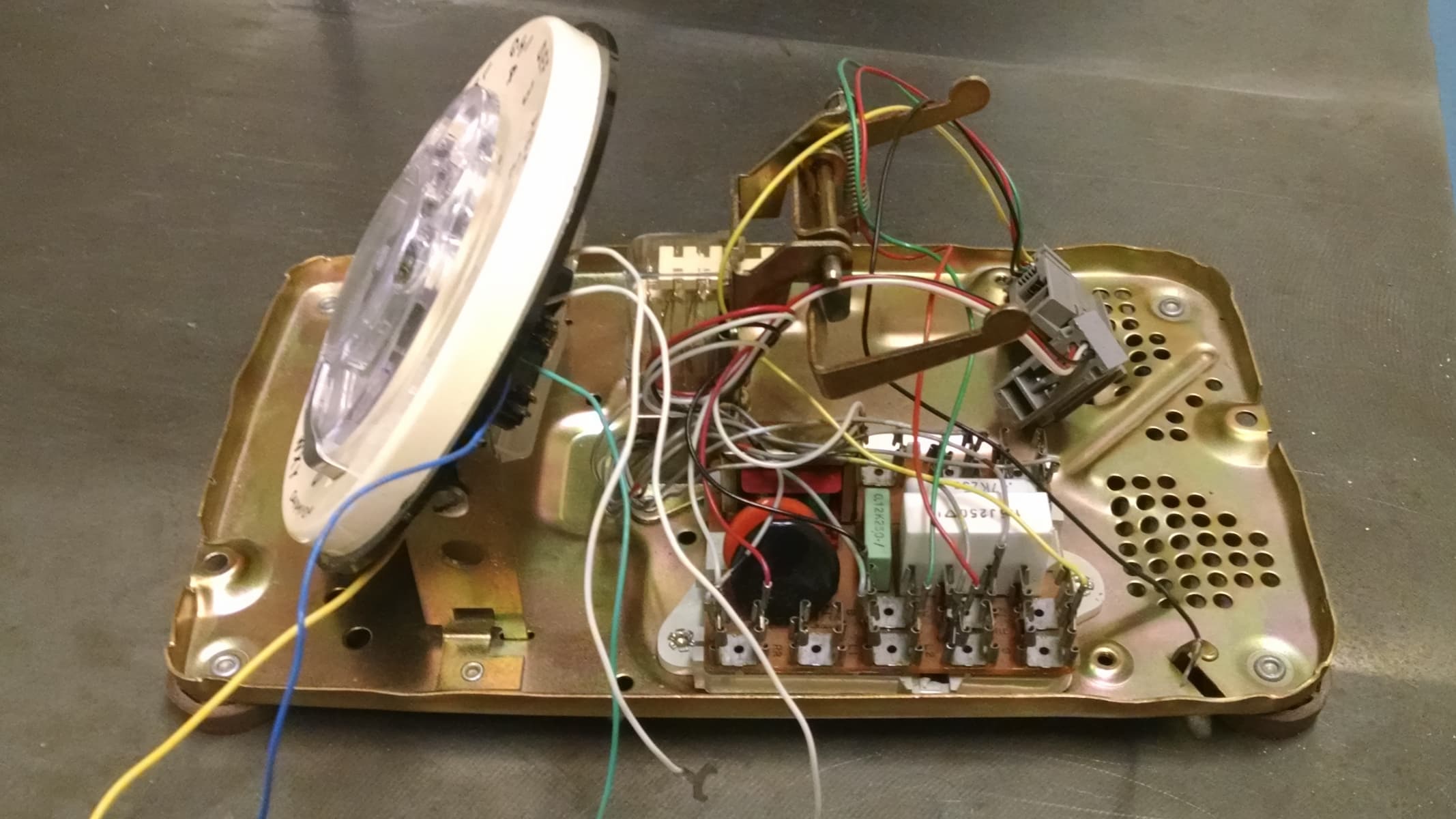
Innards of the rotary phone
messy
All tidied up
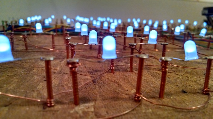
Electrical connections are made by wrapping bare wire around copper nails
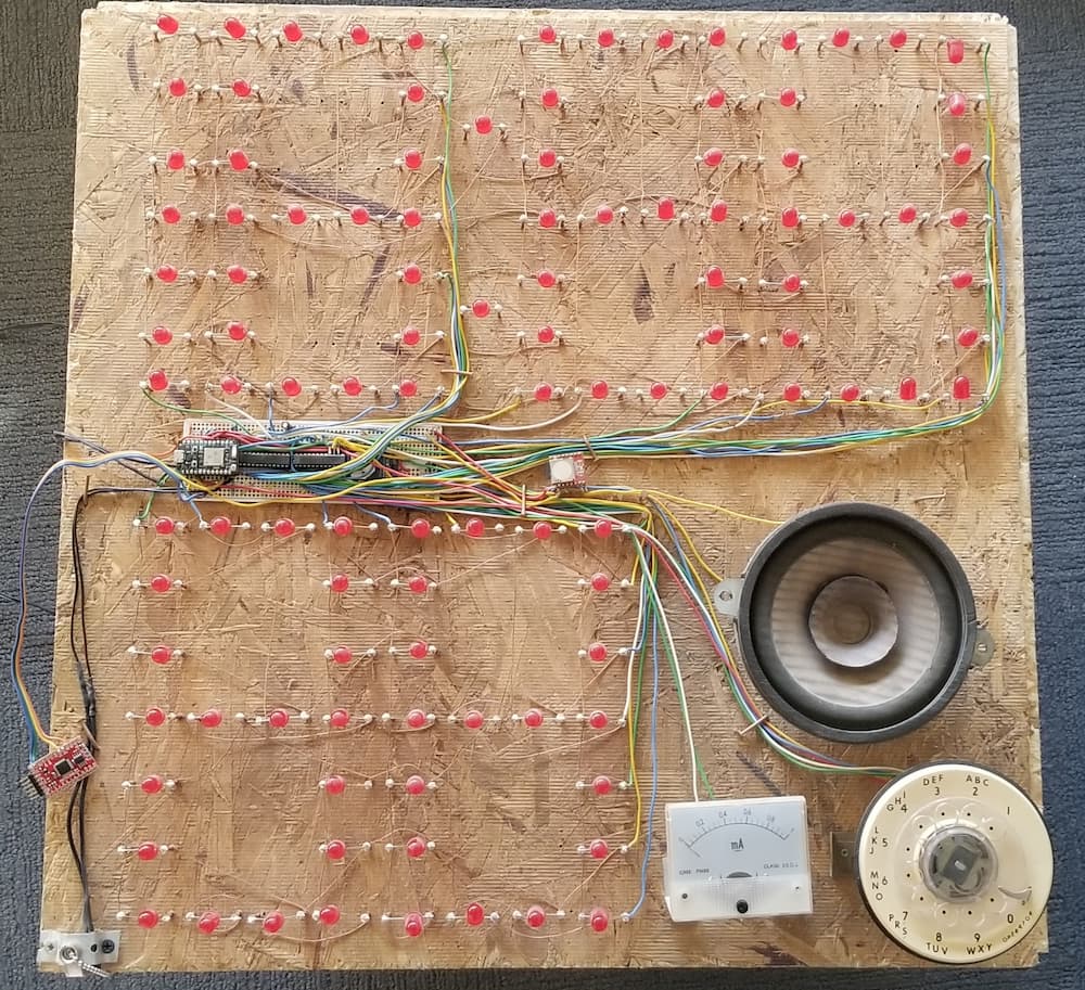
I switched to larger 10mm red LEDs
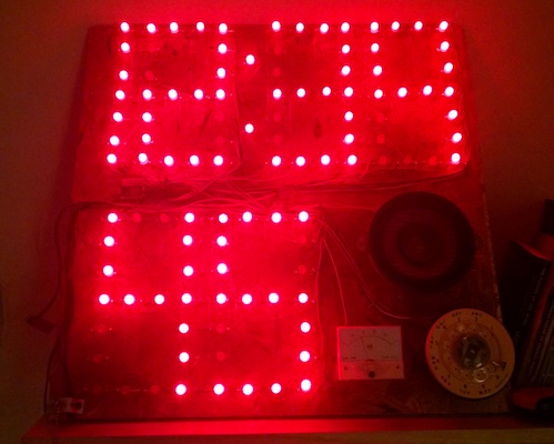
Time shown on top, local temperature on bottom
Connecting to the internet
In order to turn my clock into an internet “thing”, I migrated my code from an Arduino Uno to a Particle Photon. Particle has a pretty mature platform that makes IOT fairly painless. The Photon can be programmed wirelessly using familiar Arduino-style C++ code.
You can store variables and functions in Particle's cloud service, as well as publish and subscribe to webhooks that can talk to other internet services. I'm using Particle's cloud for following tasks:
- syncing my clock with the local time upon startup
- communicating with a mobile app for setting alarms and turning off lights
- publishing to a webhook that sends data to Adafruit IO that I can later use for debugging
- subscribing to a webhook for getting weather data from Dark Sky
Particle’s documentation is top notch, but I also found Grady Hillhouse’s Photon Weather Station very useful for getting started with webhooks. I reused his code to get local weather data and display the current temperature on ClockGlomerate.
Controlling mains electricity!
I achieved the dream of turning on and off the lights in my room without having to stand up and flip a light switch on the wall.
To do this I am using the Moteino platform from LowPowerLab. They’ve developed several Arduino compatible modules that integrate HopeRF’s RFM69W radio transceiver. I am using a Moteino R4 and SwitchMote along with their RFM69 library to control the lights in my room as well as my outdoor floodlights.
Creating a mobile app
To contol the light in my room, I press a button on the app, which then (using the phone’s wifi or 4G) sends a web request, which activates a webhook on the particle cloud, which then talks to the Particle Photon over my home’s wifi, which talks over serial to the hardwired Moteino, which talks wirelessly at 433MHz to the SwitchMote that finally toggles a relay. Other functions of the app include setting an alarm, silencing the alarm, getting the weather forecast, playing music, and adjusting the speaker volume.
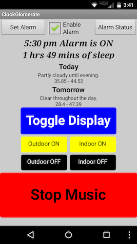
Android app made using MIT App Inventor
Potential improvements
- Add FM radio
- Add bed occupancy sensor
- Switch to better LED driver possibly IS31FL3731 or HT16K33
- Integrate all chips (Photon, LED driver, radio transceiver, real time clock) onto custom PCB instead of using breakouts and protoboard.
Adafruit’s Show and Tell
← back to projects