Autopatcher
Background
At Georgia Tech I worked in the Precision Biosystems Lab. A former doctoral student Suhasa Kodandaramaiah had designed and built a robot called the Autopatcher for automating a technique called whole-cell patch clamping. I redesigned and built a new control box for the robot.
What the Autopatcher does
While applying positive pressure to keep the tip clear of debris, the robot precisely lowers a small glass pipette into the brain. When the pipette tip gets near a neuron of interest (characterized by an increase in electrical impedance), a small amount of suction is applied in order to make contact with the cell membrane. Once this contact has been made, quick pulses of high suction are applied to break through membrane and create a “whole-cell patch”. The whole-cell patch allows neuroscientists to listen in on and record the cell’s electrical activity. A video explanation can be found here.
Redesigning the control box
Different stages of the automation routine require different pressures (positive, low suction and high suction) at the pipette tip. The control box is responsible for setting these three pressures and switching between them.
Original design
The three pressures were monitored by looking at the displays of three manometers. The pressures were adjusted by manually turning potentiometers to send an 0-5 V control voltage to the pressure controllers.
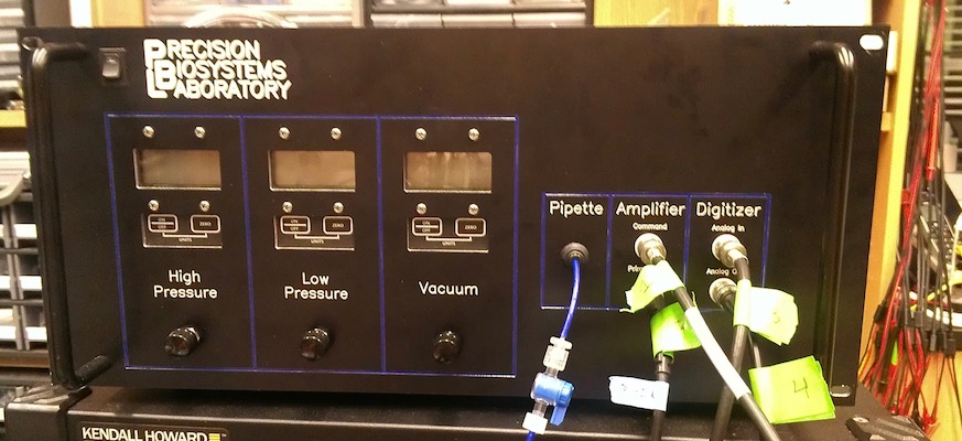
Manometer based design
My changes
The controllers we were using provided a 0-5V “Monitor Signal” that can be used to get a reading from the internal pressure sensor. Instead of using large expensive manometers, I used this signal along with an Arduino to display the pressure on a 16x2 LCD. I designed a custom printed circuit board (PCB) that attached to an Arduino. The PCB included mini solenoid valves for switching between different pressures and a 10-bit digital to analog converter (DAC) for sending a control voltage to the pressure controllers.
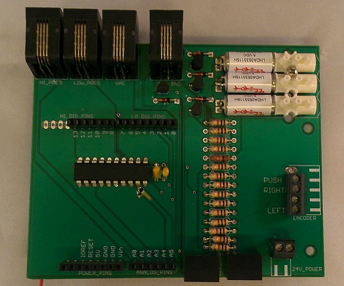
My first ever PCB rev 1.0
Controlling the pressure with software instead of physical knobs allowed the possibility of implementing customized continuous pressure profiles instead of switching between discrete pressure levels. To preserve the ability to manually adjust pressure controller levels, I added a rotary encoder and knob.
Testing out the DAC + rotary encoder + LCD
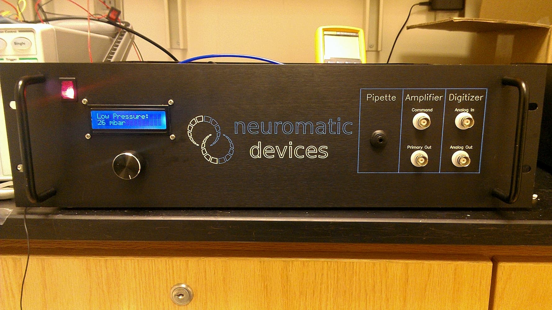
Neuromatic Devices
My modifications to the control box resulted in a smaller size and a 50% reduced BOM cost. This led to Neuromatic Devices adopting my design and hiring me to set up the manufacturing of the control boxes.
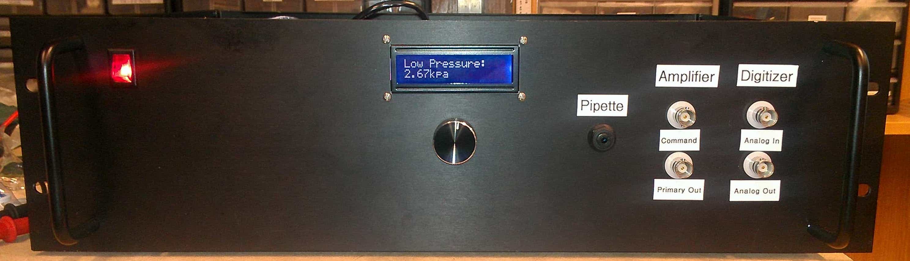
Final lab built version